Approach
S-Flex Coupling Variety Procedure
The assortment system for determining the appropriate S-Flex coupling necessitates utilizing the charts shown to the following pages. There are 3 elements to be chosen, two flanges and 1 sleeve.
Information needed in advance of a coupling is often picked:
HP and RPM of Driver or running torque
Shaft dimension of Driver and Driven equipment and corresponding keyways
Application or products description
Environmental circumstances (i.e. extreme temperature, corrosive problems, space limitations)
Methods In Choosing An S-Flex Coupling
Step one: Identify the Nominal Torque in in-lb of your application by utilizing the following formula:
Nominal Torque = (HP x 63025)/RPM
Step 2: Applying the Application Support Element Chart 1 select the services element which finest corresponds for your application.
Step 3: Calculate the Style Torque of one’s application by multiplying the Nominal Torque calculated in Phase one by the Application Support Component established in Step 2.
Style Torque = Nominal Torque x Application Service Issue
Phase four: Employing the Sleeve Performance Data Chart two select the sleeve material 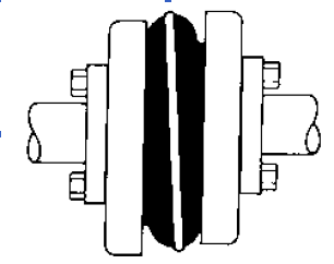 which ideal corresponds to your application.
Step 5: Applying the S-Flex Nominal Rated Torque Chart three locate the proper sleeve materials column for your sleeve picked in Step four.
Step six: Scan down this column to the very first entry exactly where the Torque Worth within the column is better than or equal towards the Design and style Torque calculated in Phase three.
Refer to your maximum RPM value on the coupling dimension to guarantee that the application specifications are met. If your greatest RPM value is much less compared to the application requirement, S-Flex couplings are usually not advised for your application.
Note:
If Nominal Torque is much less than 1/4 in the coupling’s nominalrated torque, misalignment capacities are decreased by 1/2. Once torque value is located, refer on the corresponding coupling size within the 1st column in the S-Flex Nominal Rated Torque Data Chart 3 .
Phase 7: Review the application driver/driven shaft sizes to your optimum bore size offered within the coupling selected. If coupling max bore is just not substantial sufficient for your shaft diameter, select the next greatest coupling that should accommodate the driver/driven shaft diameters.
Step eight: Using the Item Variety tables, find the proper Keyway and Bore dimension necessary and locate the quantity.